
Modbus RTU Explained: Frame Structure, Timing Rules, & Field Troubleshooting
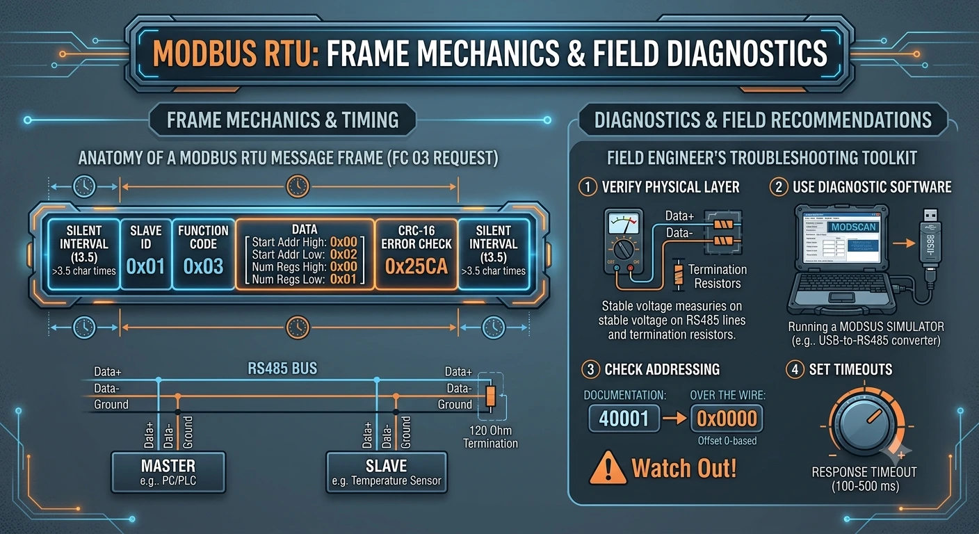
Discover how Modbus RTU works under the hood. Learn the breakdown of message frames, function codes, the t3.5 timing rule, and CRC-16 calculation, plus practical recommendations for field engineers troubleshooting RS485 networks.
Introduction
Modbus is one of the earliest communication protocols machines ever used to talk to each other. Imagine a factory floor where multiple types of machines need to share data. That’s basically the problem Modbus showed up to solve. It was originally designed for use with programmable logic controllers (PLCs), but over time it became a standard communication protocol for industrial electronic devices across a wide range of buses and networks.
It was originally published in 1979 by Modicon (later bought by Schneider Electric in 1997). In 2004, the rights were transferred to the Modbus Organization, which is a trade association of users and suppliers of Modbus-compliant devices that promotes and maintains the protocol. It was designed for industrial environments, is relatively easy to deploy and maintain compared to many other standards, and places very few restrictions on how data is structured or transmitted.
Modbus uses serial line communication, Ethernet, or the Internet Protocol Suite as its transport. On the serial side, it typically runs over RS232, RS422, or RS485. On Ethernet networks, it commonly runs over TCP/IP. This allows multiple devices to be connected on the same network or cable. For example, a temperature sensor and a humidity sensor can both sit on the same Modbus network and send their readings to a central computer or controller.
Modbus is also widely used to connect supervisory computers in industrial systems with remote terminal units (RTUs) in supervisory control and data acquisition (SCADA) systems. Many of its data types come from industrial control concepts like ladder logic. For example, a single-bit output is called a coil, and a single-bit input is called a discrete input or contact.
Modbus standards or variants include:
- Modbus RTU
- Modbus ASCII
- Modbus TCP/IP
- Modbus UDP
- Modbus ASCII over Ethernet
- Modbus TCP/IP over Ethernet
- Modbus RTU over Ethernet
- Open Modbus TCP
- MODBUS PLUS, a high-speed token-passing network
- Modbus Secure
- Modbus RTPS
In this article, we will only cover Modbus RTU.
We also write a weekly blog about engineering insights where we cover legacy and private networks, engineering tips, etc. Subscribe to us on LinkedIn <URL>.
Modbus RTU is one of the simplest Modbus protocols. It uses a Client-Server (historically referred to as Master-Slave) architecture. There is a master in the network, and other devices act as slaves. Only the master can initiate a command, and the relevant slave responds to that.
A simple Modbus message uses the slave ID, Function Code, the data, and CRC.
[slave id] [function code] [data] [CRC]
The list of function codes is as follows,
| Code (Dec) | Code (Hex) | Name | Data Type | Access |
| 01 | 0x01 |
Read Coils | Single Bit | Read / Write |
| 02 | 0x02 |
Read Discrete Inputs | Single Bit | Read Only |
| 03 | 0x03 |
Read Holding Registers | 16-bit Word | Read / Write |
| 04 | 0x04 |
Read Input Registers | 16-bit Word | Read Only |
| 05 | 0x05 |
Write Single Coil | Single Bit | Write Only |
| 06 | 0x06 |
Write Single Register | 16-bit Word | Write Only |
| 15 | 0x0F |
Write Multiple Coils | Multiple Bits | Write Only |
| 16 | 0x10 |
Write Multiple Registers | Multiple Words | Write Only |
Setting up Modbus RTU:
To establish communication between a Master and Slaves over RS485/RS232, all devices on the bus must share matching physical layer configurations:
-
Baud Rate: Commonly
9600,19200, or115200bps. -
Data Bits: Standard is
8. -
Parity: Even, Odd, or None (If None,
2stop bits are required by standard). -
Stop Bits:
1or2. -
Wiring: RS485 (2-wire half-duplex, A/B lines plus ground) with termination resistors 120 Ω at both ends of the main trunk.
Modbus RTU cycle:
There are two types of signals in Modbus. First read and second write. If a master sends a read request, the slave sends the data accordingly. But when the master sends a write request, the slave acknowledges the request, writes the data into the memory, and sends the same signal again as an acknowledgment.
Let's diagnose each signal request and response.
Frame Diagnosis
1. Read Request Cycle (Function Code 03 - Read Holding Register)
Master Query: Reads 1 holding register at memory address 0x0002 from Slave 0x01.
01 03 00 02 00 01 25 CA
-
01: Slave Address -
03: Function Code (Read Holding Registers) -
00 02: Register Start Address High/Low (0x0002) -
00 01: Number of Registers to read (1) -
25 CA: CRC-16 (Low byte, High byte)
Slave Response: Returns value 0x1234 ($4660$ in decimal).
01 03 02 12 34 B5 33
-
01: Slave Address -
03: Function Code (Echoed) -
02: Byte Count ($2$ bytes of data follow) -
12 34: Data in register (0x1234) -
B5 33: CRC-16
Write Request Cycle (Function Code 06 - Write Single Register)
Master Query: Writes value 0x00FF to register 0x0001 on Slave 0x01. 01 06 00 01 00 FF 98 0A
-
01: Slave Address -
06: Function Code (Write Single Register) -
00 01: Target Register Address (0x0001) -
00 FF: Data Value to write (0x00FF) -
98 0A: CRC-16
Slave Acknowledgment: The slave writes data to memory and echoes the exact request back to confirm execution. 01 06 00 01 00 FF 98 0A
Error Codes:
Modbus also uses error codes, which people rarely discuss. The following are some error codes which helps us to diagnosis modbus effectivly.
When a slave receives a valid message frame (correct CRC) but cannot process the command, it returns an Exception Response.
-
The Slave sets the Most Significant Bit (MSB) of the Function Code to
1(Function Code $+ 0x80$). -
It appends an Exception Code to explain why it failed.
Exception Frame Format: [Slave ID] [Function Code + 0x80] [Exception Code] [CRC]
| Requested Code | Error Name | Meaning & Cause |
Read Coils (0x01) |
Illegal Function | The requested function code is not supported by the slave device. |
Read Discrete Inputs (0x02) |
Illegal Data Address | The requested register/coil address is out of range or does not exist on the slave. |
Read Holding Registers (0x03) |
Illegal Data Value | The data field value (e.g., register count or write value) is out of the allowed range. |
Read Input Registers (0x04) |
Slave Device Failure | An unrecoverable hardware or logic error occurred while processing the request. |
Write Single Coil (0x05) |
Acknowledge | The command was accepted, but execution will take time (prevents master timeout). |
Write Single Register (0x06) |
Slave Device Busy | The slave is performing a long-running process; retry the request later. |
The 3.5 Character Framing Rule (Silent Interval)
Unlike protocols that use specific start or end characters (like STX/ETX), Modbus RTU relies on strict silent timing gaps to mark the beginning and end of a message frame.
-
Message Frame Separator (t3.5): A frame begins and ends with a continuous silent interval of at least 3.5 character times.
-
Inter-Character Timeout (t1.5): The delay between individual bytes within the same message frame must not exceed 1.5 character times. If an idle gap exceeds t1.5, the receiver flushes its buffer and treats the next byte as the start of a new frame.
Step-by-Step Calculation (at 9600 Baud)
For a standard frame configuration consisting of 1 Start Bit + 8 Data Bits + 1 Parity Bit + 1 Stop Bit = 11 bits total per character:
-
Calculate time per bit:
1 / 9600 bits/sec = 0.000104167 seconds (104.17 µs) -
Calculate time per 11-bit character:
11 bits x 0.000104167 seconds = 0.0011458 seconds (≈ 1.146 ms) -
Calculate required t3.5 idle delay:
t3.5 = 3.5 x 1.146 ms ≈ 4.01 ms
Pro Tip for Field Engineers: If your device is set to No Parity with 1 Stop Bit, each character consists of 10 bits total instead of 11. This adjusts the math to
10 / 9600 x 3.5 ≈ 3.65 ms. For standard baud rates higher than 19200 bps, the Modbus standard recommends using fixed timing values: t1.5 = 750 µs and t3.5 = 1.75 ms.
Cyclic Redundancy Check (CRC-16) Calculation
Modbus RTU uses a 16-bit Cyclic Redundancy Check (CRC-16) with the polynomial 0xA001 (the bit-reversed representation of x¹⁶ + x¹⁵ + x² + 1).
CRC Algorithm Steps:
-
Load a 16-bit register with 0xFFFF (CRC Register).
-
Exclusive OR (XOR) the first 8-bit byte of the message with the low-order byte of the 16-bit CRC register. Store the result back in the CRC register.
-
Shift the CRC register 1 bit to the right (towards the LSB), filling the MSB with zero. Extract and examine the shifted LSB.
-
If the LSB was 0: Repeat step 3 (another right shift).
-
If LSB was 1: XOR the CRC register with polynomial 0xA001.
-
Repeat steps 3 through 5 until 8 total shifts are performed on the byte.
-
Repeat steps 2 through 6 for every subsequent byte in the message frame.
-
The final 16-bit value is appended to the message in Low-Byte, High-Byte order (Little-Endian).
Technical Recommendations for Field Engineers
-
Test with PC Diagnostic Software First: Before attaching a new field device to an active PLC or SCADA network, connect it directly to your laptop using a USB-to-RS485 converter. Use diagnostic software (such as Modscan, Modbus Poll, or QModMaster) to verify communication, slave IDs, baud rates, and register addresses first. Isolating the device on a PC saves hours of bus troubleshooting later.
-
Always Check Termination & Biasing: Missing 120 Ω termination resistors cause signal reflections over long cable runs. Ensure line-biasing (pull-up/pull-down) resistors are enabled on the RS485 bus to prevent floating noise during idle states.
-
Watch Out for 0-Based vs. 1-Based Addressing: PLC documentation often references register 40001, but over the wire, Modbus RTU transmits raw offset addresses starting at 0x0000 (meaning 40001 maps to
0x0000). Off-by-one errors are the single most common deployment issue in industrial automation. -
Set Realistic Timeout Thresholds: Allow sufficient response time (100 to 500 ms) depending on the slave device's internal scan time to prevent master polling collisions.
Comments & Discussions 0
Leave a Comment
No comments yet. Be the first to start the discussion!